
Building Carbon’s Metamaterials Library
By Kyle Kloster, Ehsan Haghighat, Clarissa Gutierrez, Connor TeVault, Ruiqi Chen, Wilson Wong, Garrett Fielding, Weixiong (Victor) Zheng, Kirby Freeman, Sai Nelaturi
September 22, 2022
1 Inverse Design
Forward-looking designers and engineers have found that they can create parts with precisely-tuned performance, enhanced washability and breathability, and advanced aesthetics by populating their designs with conformal lattices tailored to achieve different mechanical responses at various locations on their part. Additive manufacturing and robust design tools have enabled companies to apply these innovations to products for impact absorption (helmets), lightweighting, packaging, and many other applications. Engineers understand that 3D printing can help fabricate complex geometries, but their challenge is finding the right scale to design the right structure with the right bulk material properties. In other words, finding geometries that have material properties that meet desired mechanical response requirements is a significant challenge for engineers. It is also an example of an inverse design problem, and one where a given requirement can lead to multiple solutions.
The Carbon Design Engine™ now provides access to a growing metamaterials library to help users find lattice cell designs that will give their printed counterparts user-specified bulk mechanical properties. In this article, we describe our approach to generate and validate data for the behavior of a lattice design under compression loading. This includes specifics of the finite element analysis we perform for estimating the lattice’s mechanical response, as well as the specifics of physical testing conducted to validate our simulation tools. We provide data for primary cell types (Tetrahedral, Voronoi, Rhombic, Kagome, Kelvin, Icosahedral, Star) as well as many hybrid cell types obtained by interpolating the geometries of primary cell types.
2 Carbon’s simulation pipeline
Given the high-dimensional space of possible lattice designs, we are working to address the inverse design problem of selecting a lattice cell type given user-specified requirements for stiffness and/or volume fraction. To this end, we have built a library that includes mechanical characteristics of a wide variety of lattice unit cell designs, including their volume fraction and stiffness (effective Young’s modulus) properties. Volume fraction is the ratio of the volume of the lattice unit cell to the volume of its bounding box. The Young’s modulus is estimated as the slope of the stress-strain curve measured at 2% strain. The library is populated with results from simulated compression of such lattices. These simulations have been validated experimentally on a small subset of lattice choices. The following section describes the simulation pipeline used to build this library.
To estimate the stiffness of a lattice made out of Carbon’s EPU 40 material, we used a 40 mm x 40 mm x 20 mm (L x W x H) rectangular prism design space to create a latticed “puck,” as shown in Figure 1. The puck is a representative geometry whose bulk material properties can reflect the effective properties of a similarly-latticed part. Depending on the loading stage and geometrical characteristics, such as strut length and diameter, the mechanical response of a latticed structure can be quite complex, involving an early-stage elastic response, followed by a yielding response as a result of struts buckling, followed by a final stage of densification as a result of struts reaching contact with each other.
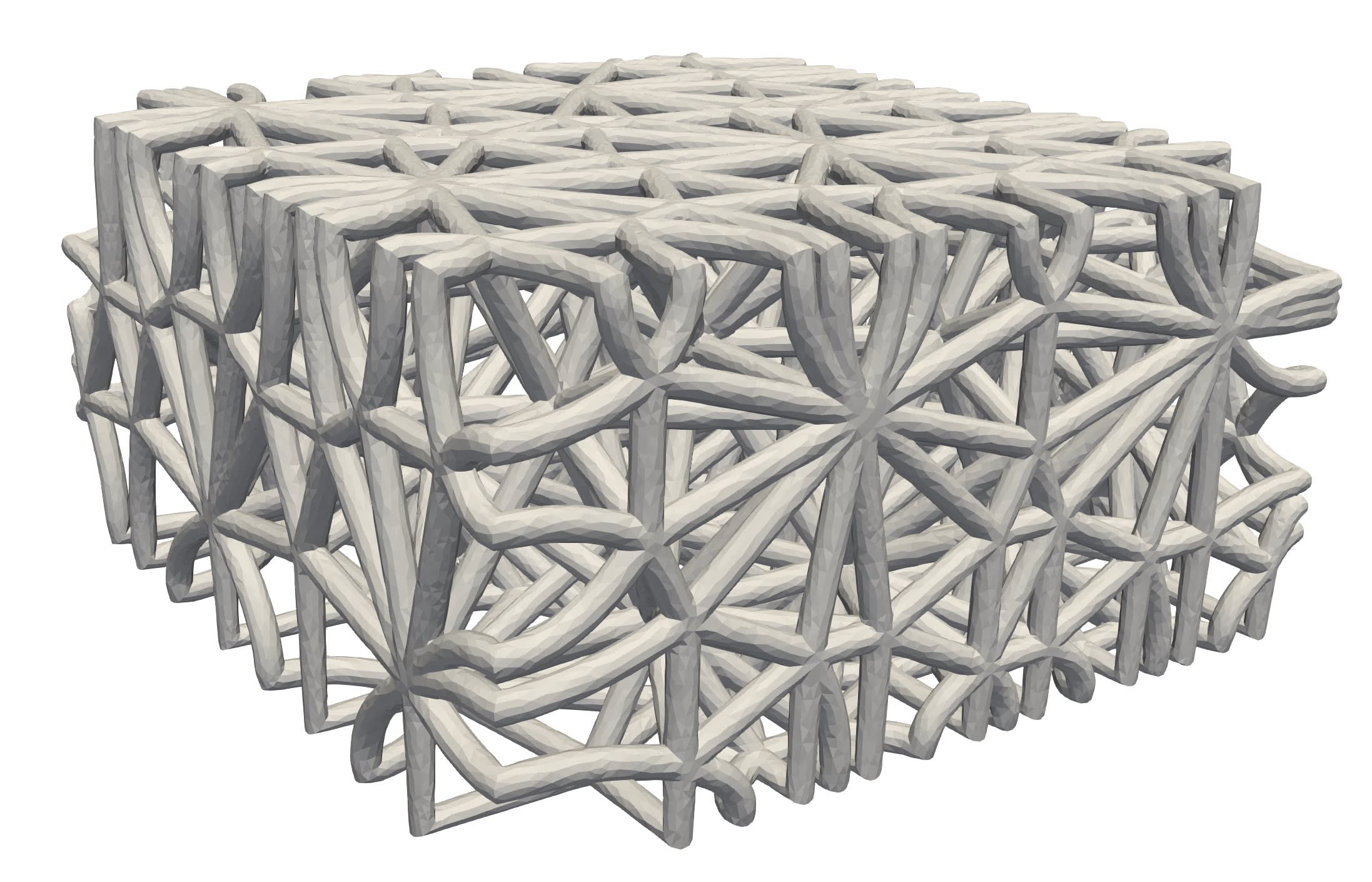
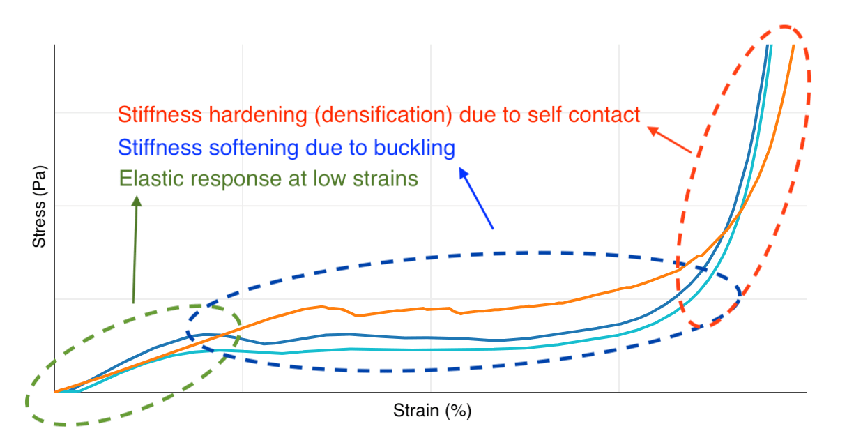
Figure 1: (Left) A puck latticed with the Tetrahedral unit cell. (Right) A generic stress-strain characterization response.
To model such a complex system, we needed a simulator that can accurately model large deformations, buckling, and contact. Among these requirements, handling self-contact is the primary bottleneck for simulators; in fact, most commercial software fails to handle self-contact for such a complex system involving several deforming struts. An alternative choice was to drop these constraints and use a linear solver without contact. However, in that case, the computed force-displacement response would be unrealistically stiff, and the tool would not be capable of accurately capturing features such as plateau stress and densification stiffness.
Recently, researchers from NYU proposed a state-of-the-art automated framework, the Incremental Potential Contact (IPC) algorithm [1], capable of handling very complex multi-body contact physics. IPC provides a penetration-free contact algorithm by introducing mechanistically-sound, barrier-energy functionals.
Our data leverages IPC to simulate the mechanical response of lattices. IPC is capable of simulating both quasistatic and impact loading. We are currently focusing only on the quasistatic response of lattices.

Figure 2A: Simulation setup, including a moving rigid part on top, a platen sensor at the bottom, and the latticed part in the middle.
We have designed our experimental setup to closely replicate a physical compression test, visualized in Figure 2A. The latticed puck is placed between two rigid parts, i.e., the top and bottom platens. A strain rate is imposed on the top platen, while the bottom platen is fixed. The displacement (strain) history is traced through the top platen while the puck’s stiffness is estimated from the reaction force measured from the bottom sensor.
Figure 2B: (Left) A physical compression test on a Kagome lattice puck. (Right) The same puck in our simulated compression engine. Note that both animations have been sped up.
3 Physical testing validation
In modeling a complex physical process, discrepancy between the model and the physical process is unavoidable. In the case of the mechanical properties presented in the library, variables in each stage of Carbon’s manufacturing process (slicing, printing, baking, etc.) can introduce additional variation in the final printed part, and therefore an additional discrepancy between the simulated response in the library and the behavior observed in actual manufactured parts.
With this in mind, we wanted to understand how well we can expect our simulated data to match physical behavior of latticed parts. The following section presents comparisons of our simulation engine with physical testing designed to replicate the simulated compression. Each plot shows, for a single latticed puck, the predicted response from our simulator side by side with the observed data from a physical test conducted on a puck printed from the exact mesh used in the corresponding simulation.
The dataset used includes the Kagome, Icosahedral, and Tetrahedral primary cell types, as well as several hybrids of the Tetrahedral and Icosahedral cell types. Each puck was generated using a cell size of 10 mm, a uniform strut diameter, a single lattice cell type, and common Design Engine settings for lattice solidification (see Section 4 for more detail). Pucks were printed using Carbon’s EPU 40 resin—the simulations used material property parameters (Poisson’s ratio and Young’s modulus) corresponding to this same resin. The following figures provide details for those interested in reproducing our precise experimental setup.
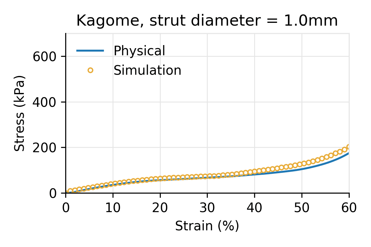
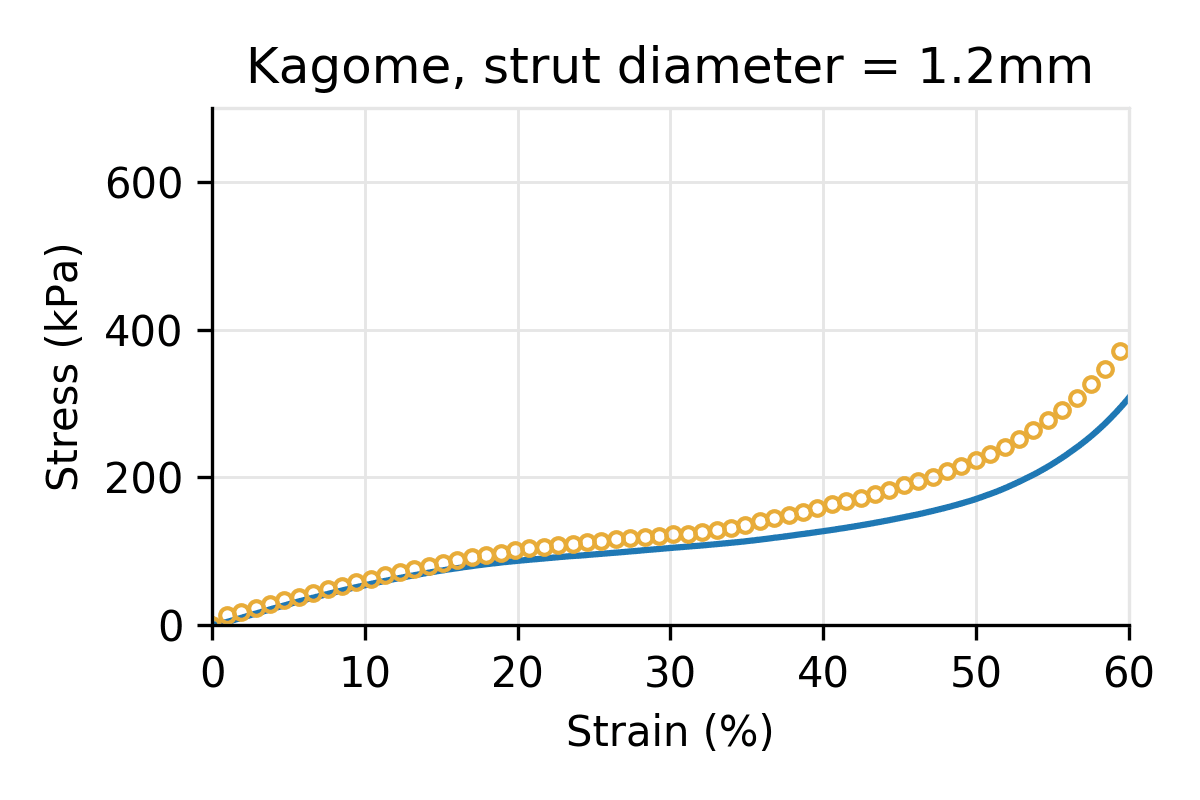
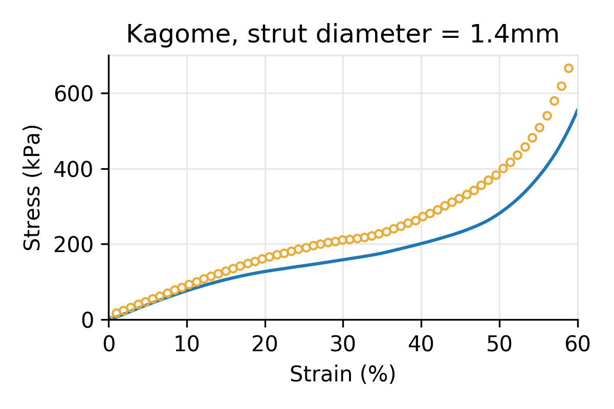
Figure 3: Simulated vs physical compression for a Kagome latticed puck for three different strut diameters, and a cell size of 10 mm.
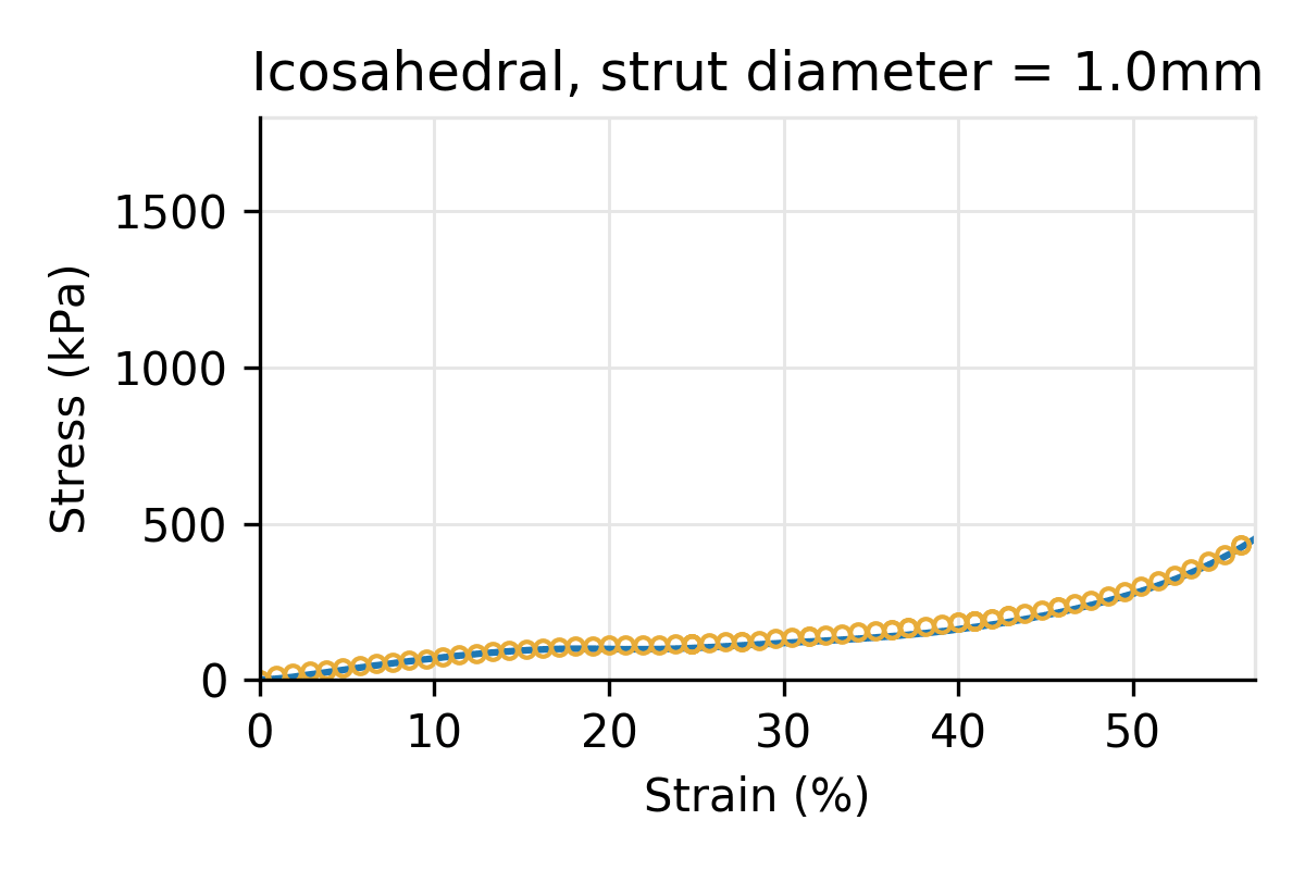
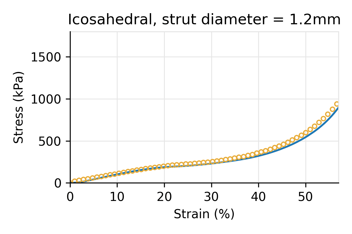
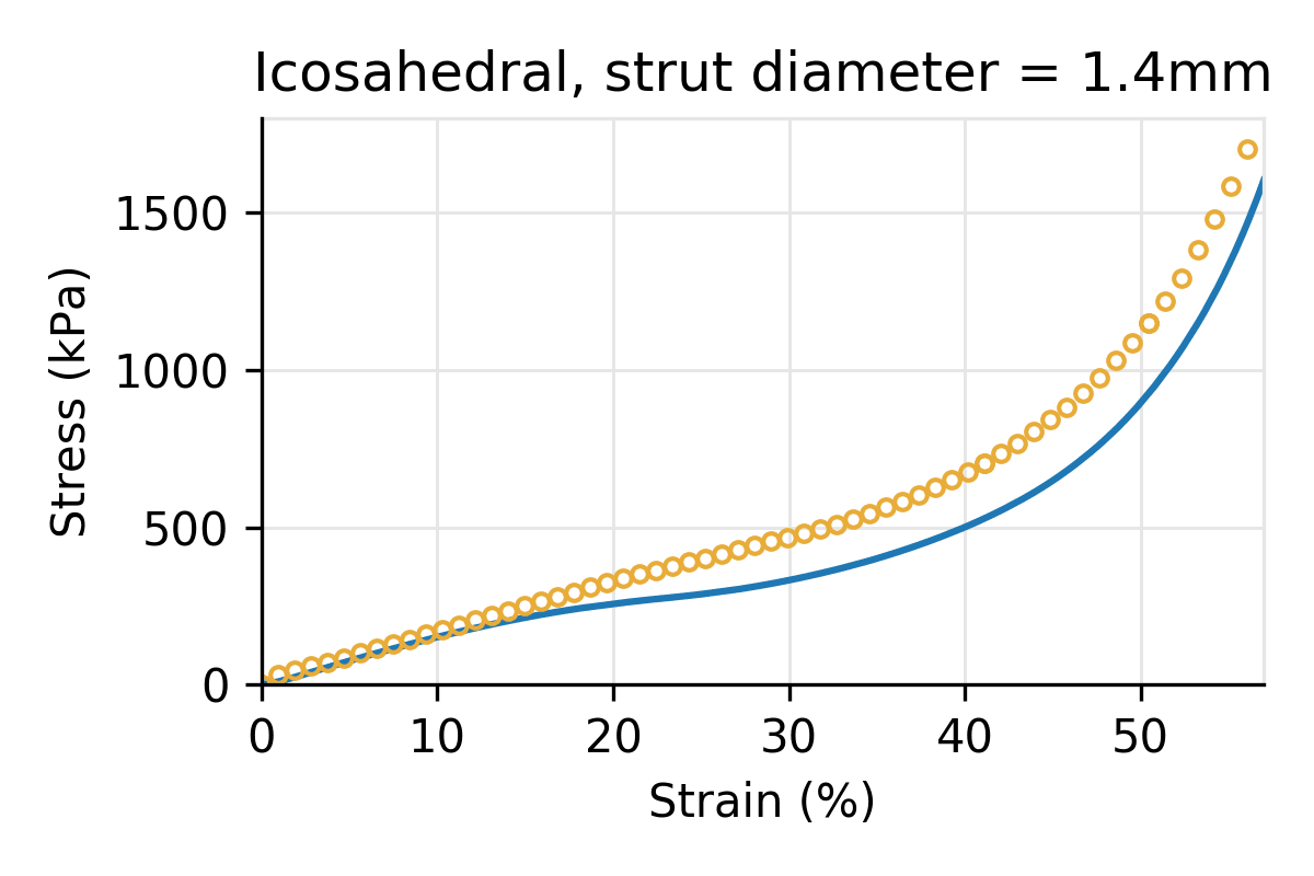
Figure 4: Simulated vs physical compression for an Icosahedral latticed puck for three different strut diameters, and a cell size of 10 mm.
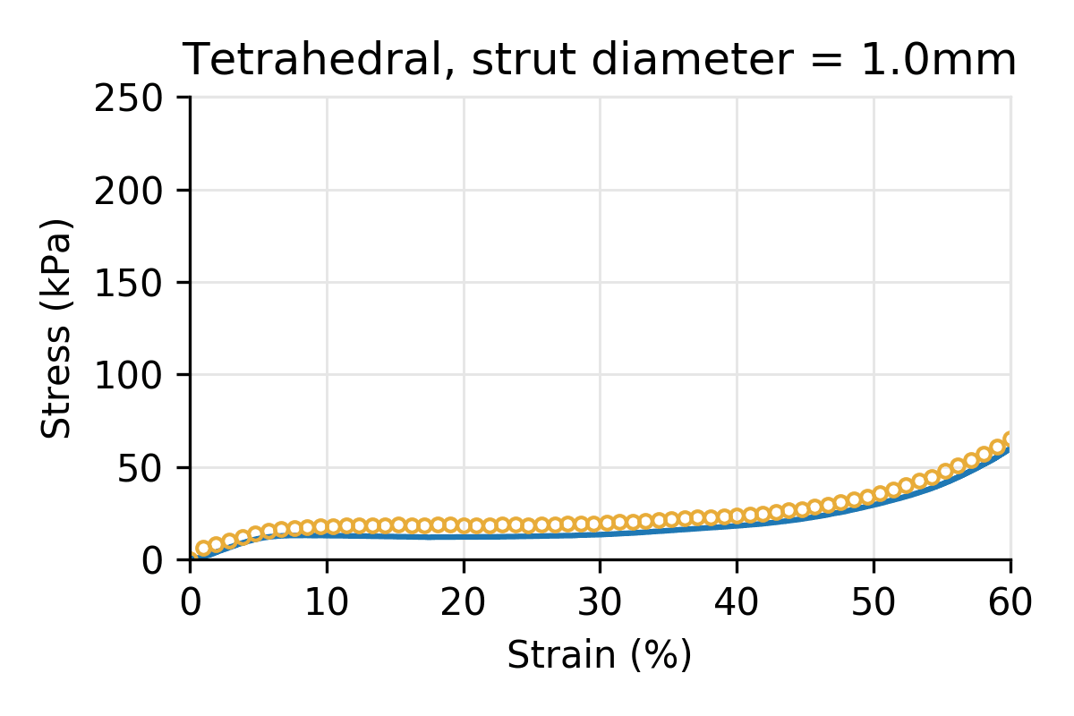
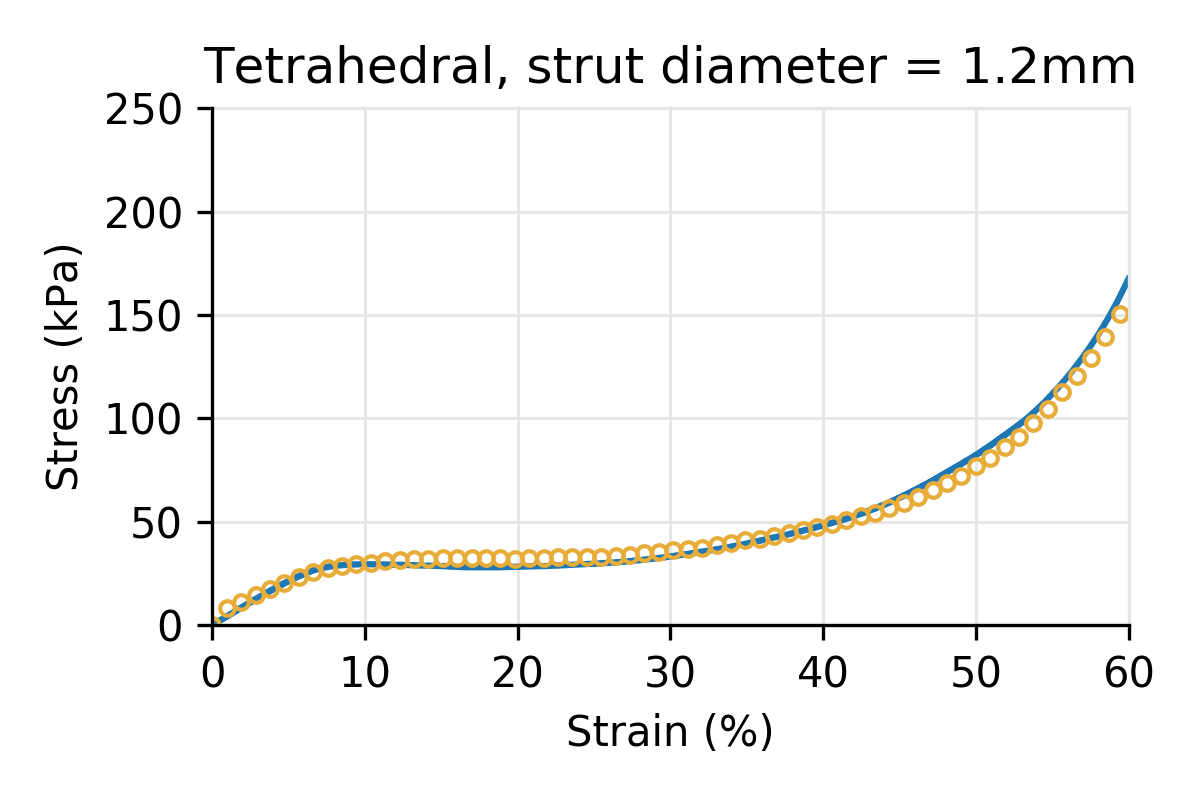
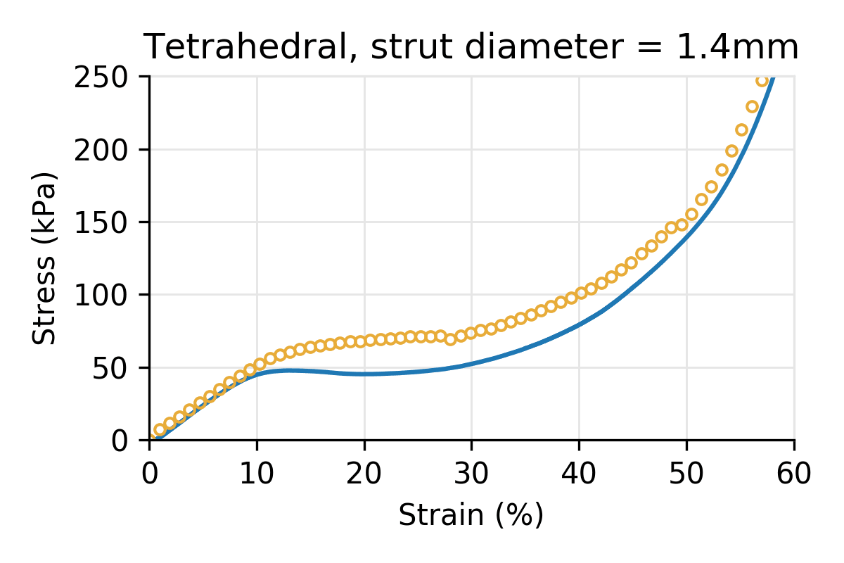
Figure 5: Simulated vs physical compression for a Tetrahedral latticed puck for three different strut diameters, and a cell size of 10 mm.
The following plots refer to hybrid lattices using the naming scheme used in our library: hybrid lattices are named by their primary cell type components, using the first three letters of each primary cell type, followed by their proportions as a percentage. For example, a hybrid cell with composition 80% Icosahedral and 20% Tetrahedral is named “IcoTet_8020.”
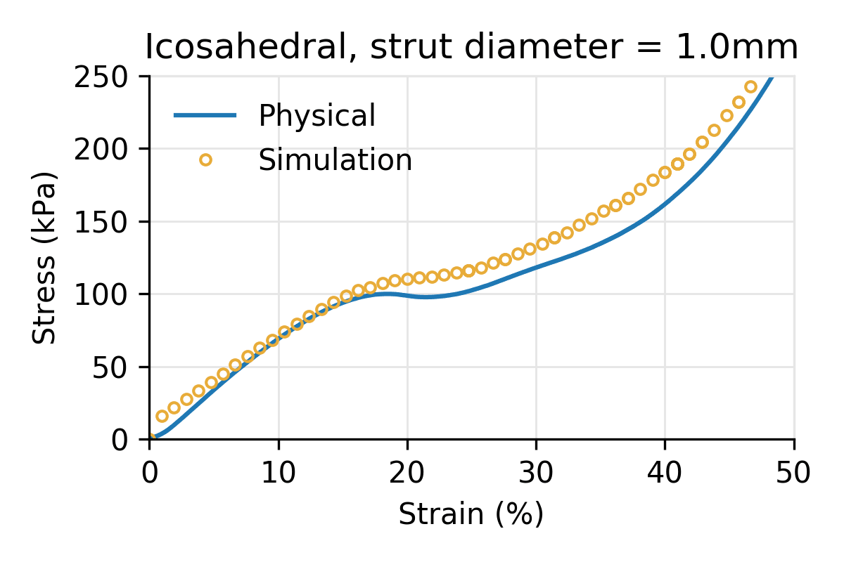
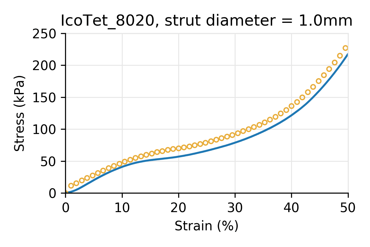
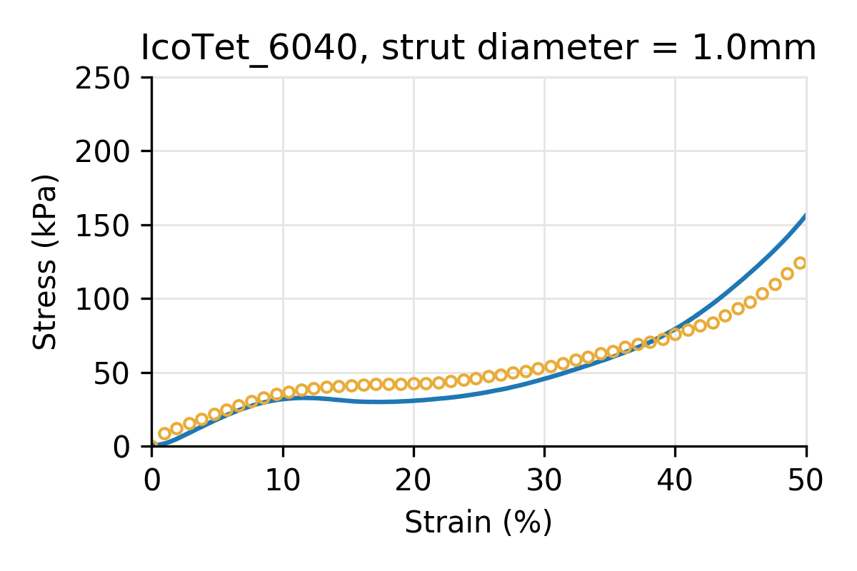
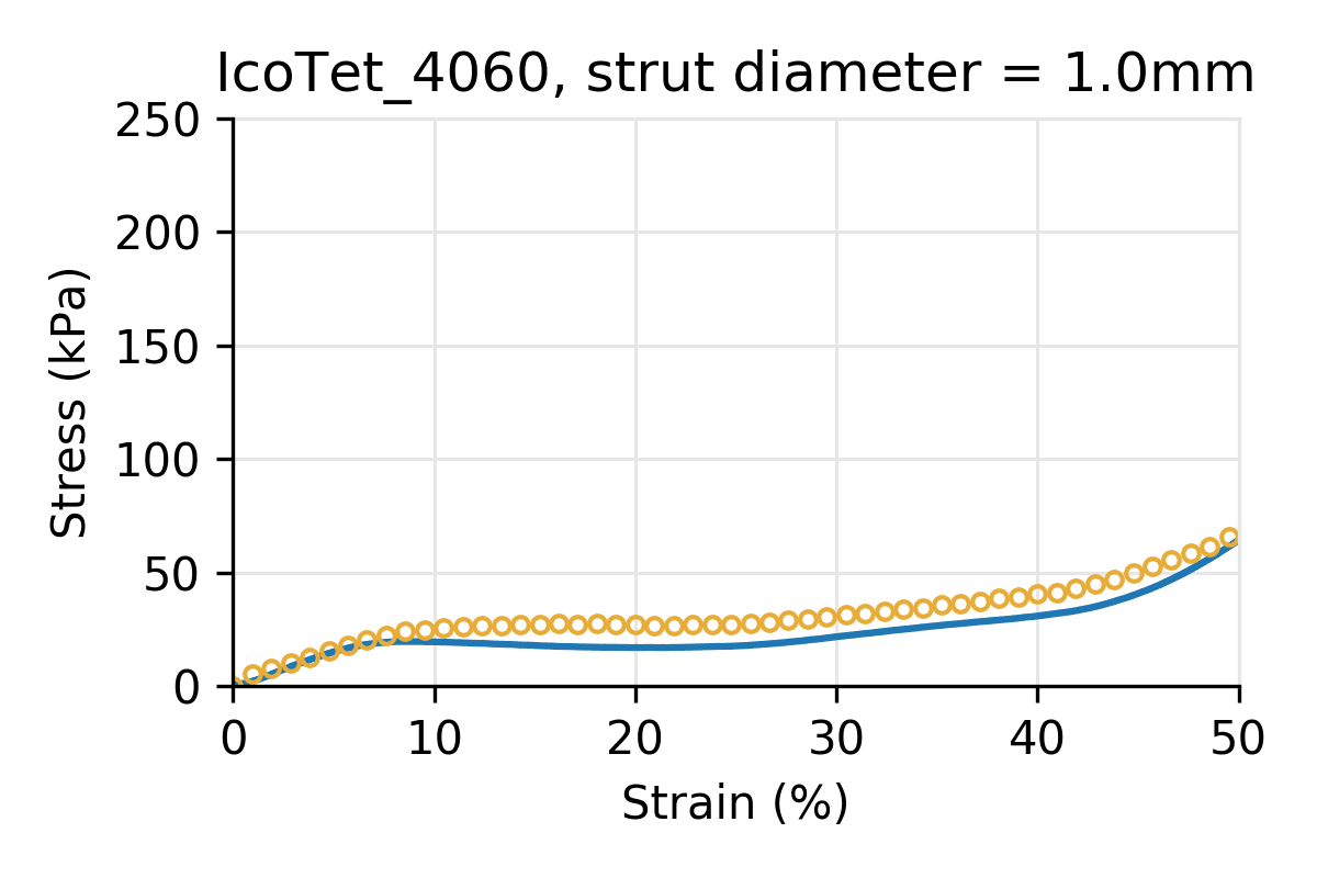
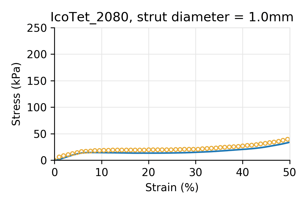
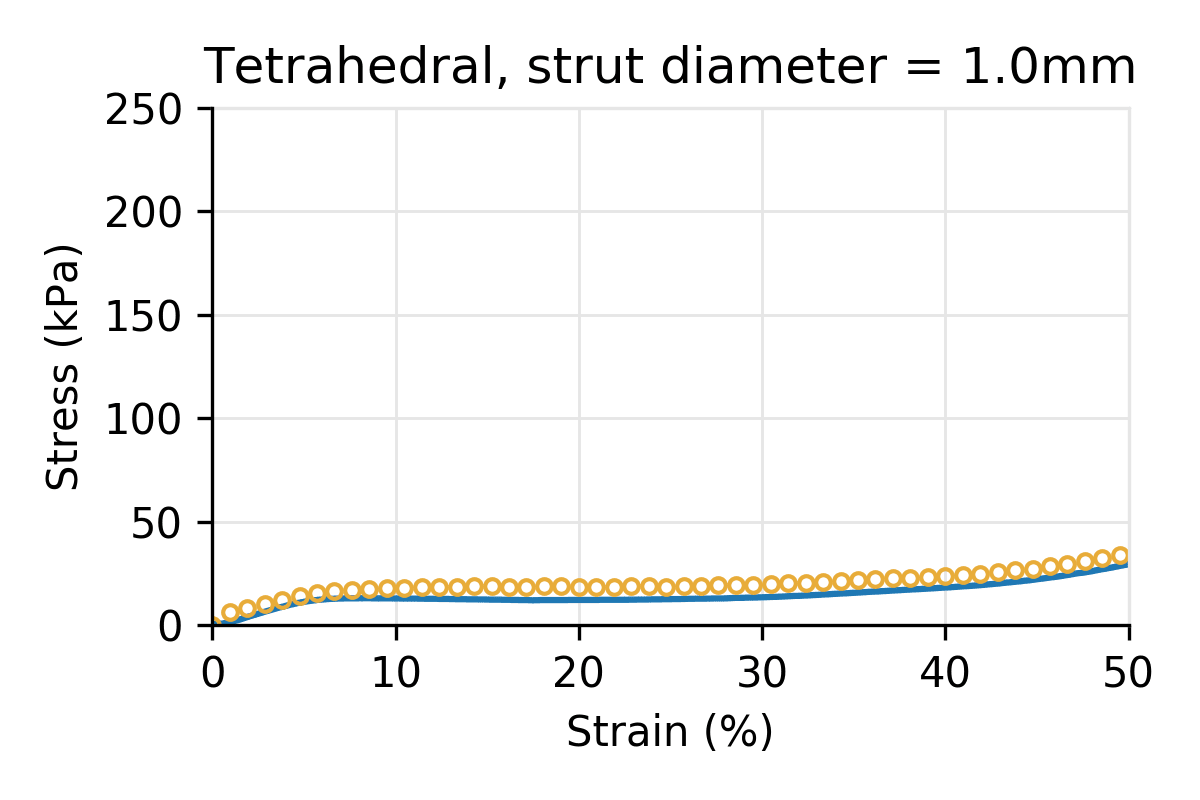
Figure 6: Simulated vs physical compression for hybrid cell types, composed of Icosahedral and Tetrahedral primary types, shifting from pure Icosahedral (top-left) to pure Tetrahedral (bottom-right). All pucks have the same cell size (10 mm) and strut diameter.
4 Details of simulation and experimental setup
Additional simulation details. To generate the simulated results displayed in this report, we used the following settings in our simulation engine. We approximated the material properties of our EPU 40 resin with a material modulus of 6 MPa, a Poisson’s ratio of 0.48, and a density of 0.00103 g/mm3. For the compression settings, the (simulated) platen compresses at a linear speed of 20.0 mm/s, and we included the effect of gravity in the simulation engine.
Puck generation. The STL for each test specimen was created by populating a 40 mm x 40 mm x 20 mm rectangular prism with a selected lattice unit cell and using the default settings for the “Strut Lattice” and “Solidify” operations in the Design Engine latticing operations, with two minor changes:
- The Strut Lattice operation’s “feature edge” option was turned off.
- The Solidify operation used 15 sides per strut, instead of the default value.
For further detail on the lattice engine used in Design Engine, see Carbon’s white paper.
Puck printing. Pucks were printed according to standard Carbon procedures. To print the pucks used in the experiments, we followed the protocol described in the Carbon Academy EPU 40 course, as well as the standards for post-processing specified there. The default Design Engine settings include an “Apply base” option; we printed the resulting pucks with the based side on the build platform.
Physical testing setup. Before conducting compression, the pucks were conditioned overnight in a controlled environment, at 23oC and 50% RH.
For this study, our static compression test setting used a full platen and compressed at 100 mm/min until 70% strain (or the capacity for the load cell was reached, whichever occurred first). The compression speed in the physical setting was different from the 20 mm/s speed used in our simulation setting; the physical setting parameters are standard, whereas the simulation parameters were chosen to optimize for lower computational runtime. For each specimen, 2 cycles of compression were applied: one cycle to 70% deformation (or when the load capacity of the cell was reached, whichever occurred first), then a second cycle after the first cycle unloaded. We report results from the first cycle in the validation plots presented here.
5 How to use simulation data
We strive to help engineers iterating their parts to identify the design parameters that attain the parts’ target properties. To gain insight for achieving desired performance at the level of a full part, engineers can first characterize behavior of lattice parameters in a simple design space like a puck. The characterization data shown in Design Engine are derived from simulated lattice behavior in such a simplified setting.
In this validation study, we found that our simulated mechanical response data reasonably matched experimental data on the small set of lattices we tested in a physical setting. However, these tests were performed with ideal, simple parts in a controlled environment. We do not expect the precise numbers shown to accurately describe performance of parts that are more complex or used in less ideal settings. The data like the stress-strain curves shown in Design Engine are best used as a comparative tool in evaluating a lattice’s performance relative to other lattices. Actual lattice behavior depends on specific use and is subject to variation inherent in manufacturing processes and different environments in which products are used. Users should validate lattice behavior in settings specific to their needs.
References
[1] Li M, Ferguson Z, Schneider T, Langlois TR, Zorin D, Panozzo D, Jiang C, Kaufman DM. Incremental potential contact: intersection-and inversion-free, large-deformation dynamics. ACM Trans Graph. 2020;39(4)49.1-49.20.
3D as It’s Meant to Be
Interested in utilizing Carbon to accelerate product development? Reach out to us at sales@carbon3d.com to learn more!