

Find the Right Application
The Carbon DLS process is ideal for a wide range of applications, from high-value athletic equipment that delivers performance and protection to rugged automotive components that meet stringent engineering requirements.
Looking for inspiration? Check out “Ask an Additive Expert,” our video series featuring answers to common design and engineering questions presented by Carbon’s experts.
DLS Design Quick Guide
Carbon DLS lets you design the best parts for your product, without worrying about moldability or machinability. Like every 3D printing process, DLS has its own best practices; follow these principles to get the best results in your applications.
This design quick guide offers a multi-step workflow to help you design and evaluate parts quickly. Follow the steps below to determine whether your part is a good fit for the DLS process and identify aspects of your design that might need revision.


Evaluate
Begin by using these basic guidelines to determine whether your part is a good fit for Carbon DLS.
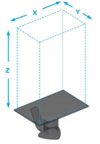
Build envelope
Will your part fit in Carbon’s 3D printers? For efficient production, consider how you’ll fit multiple parts in the build volume.
| M1 | M2 | M3 | M3 Max | L1 | |
|---|---|---|---|---|---|
| X | 141 mm (5.6 in) |
189 mm (7.4 in) |
189 mm (7.4 in) |
307 mm (12.1 in) |
410 mm (16.1 in) |
| Y | 79 mm (3.1 in) |
118 mm (4.6 in) |
118 mm (4.6 in) |
163 mm (6.4 in) |
256 mm (10.1 in) |
| Z | 326 mm (12.8 in) |
326 mm (12.8 in) |
326 mm (12.8 in) |
305 mm (12.0 in) |
460 mm (18.1 in) |
Material properties
What mechanical characteristics do you require for your parts? What traditional thermoplastics would you usually specify?
See all Carbon Technical Datasheets
Download the Material Comparison Chart
Chemical compatibility
Does your part needs to perform well when used with any of these common chemicals?
Download the Chemical Compatibility Chart (DLS Design Quick Guide)
Design
Once you have determined that your part is a good fit for the Carbon DLS process, the next step is to review your part’s features. Refer to the recommended feature sizes below to ensure your part’s printability.
Overhangs, unsupported angles, and unsupported wall thickness will inform the print orientation and support strategy for your part.
Recommended feature sizes
Are your features properly sized for successful printing?
Download the DLS Design Quick Guide
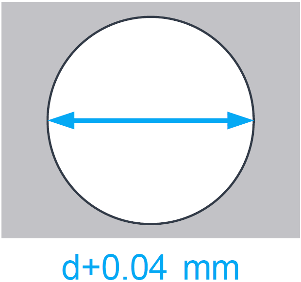
Holes
To compensate for overcure, horizontal holes should be oversized ~0.04 mm.
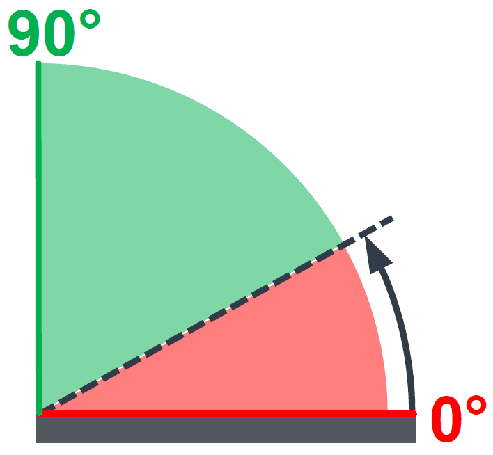
Unsupported angles
Measured relative to the platform (XY). Unsupported angles over 40 degrees are safe for all materials.
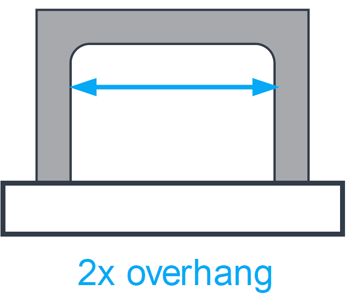
Bridges
Bridges should span no more than twice the recommended overhang distance.
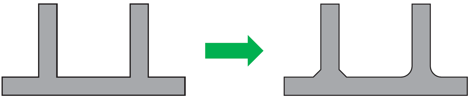
Fillets
Interior corners: ~0.5 mm minimum
Exterior corners: ~0.5 mm + wall thickness
Mating parts
Print mating parts in the same orientation.
Wall thickness
Walls at minimum thickness should be kept short.
Optimize
Refine your design using these guidelines to ensure dimensional accuracy, excellent surface quality, and overall performance that meets your requirements.
Issues to address before adding supports
Consider these recommendations as you design your part.
Low resolution model
Adjust export settings in your CAD software to make a smooth model.
Sharp corners
Add fillets or chamfers
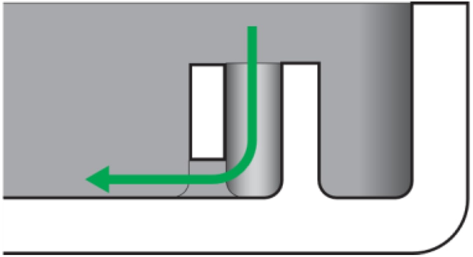
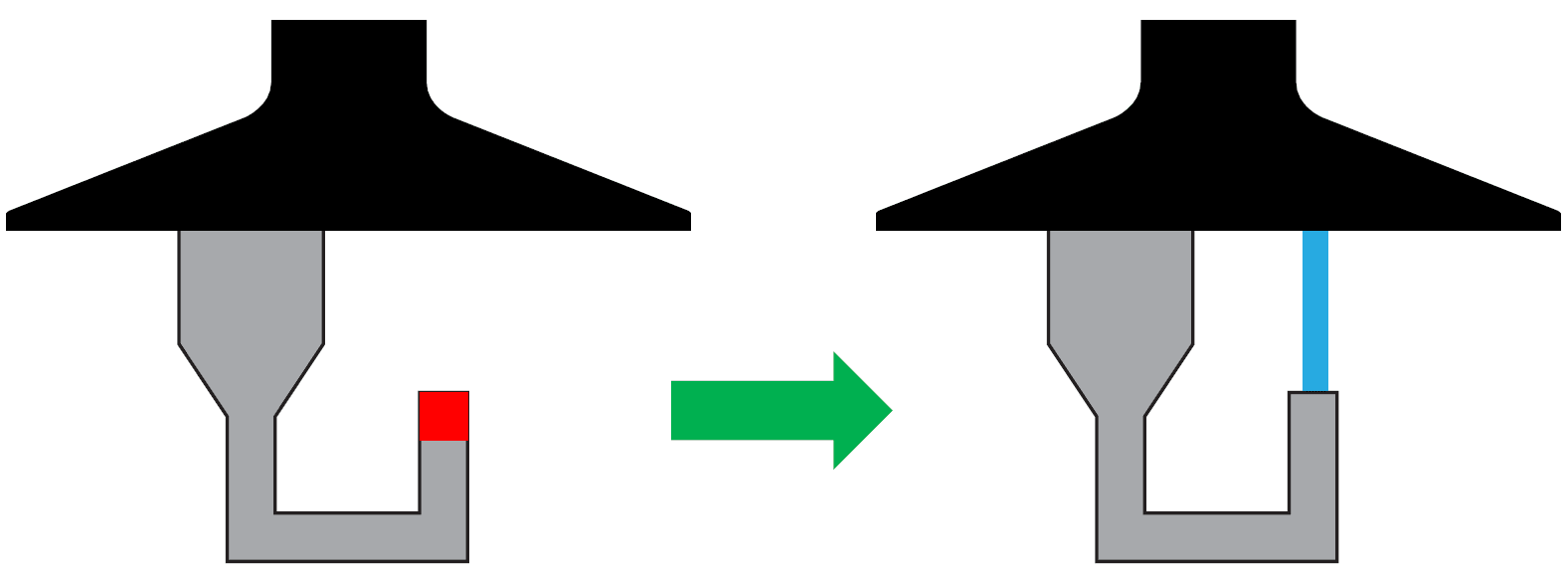
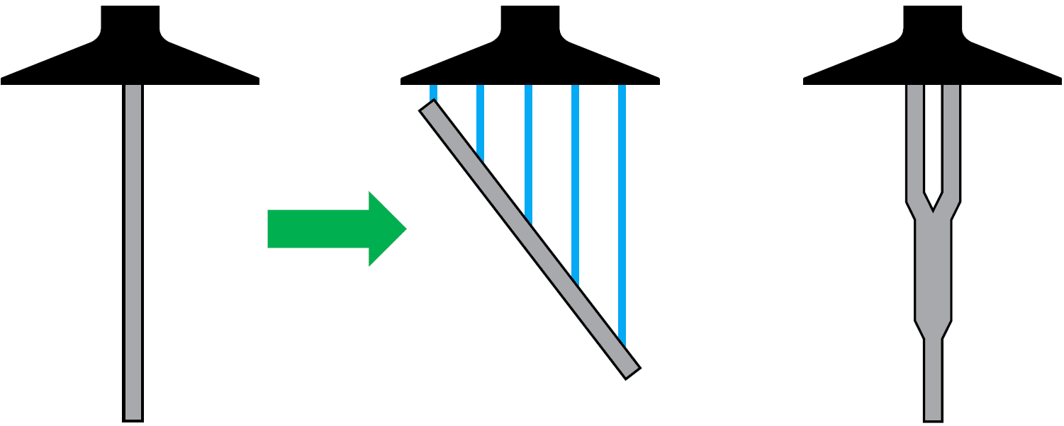
Unvented volumes and blind holes
Add 2-3 mm vents or re-orient part.
Slice islands
Islands must be supported or connected to part in order to prevent print defects.
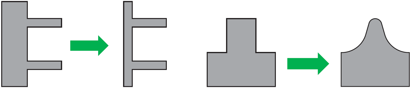
Non-uniform, rapidly changing or stepped wall thickness
Make wall thickness uniform, or keep changes in thickness as gradual as possible in order to minimize print defects and prevent warping during baking.
Tall, thin parts
Change orientation, or redesign to reduce part height and/or create stability.
Supports
Use Carbon’s print preparation software to add supports to your part design.
- Check overhangs and unsupported angles using the Overhang Detection feature
- Place supports no closer than the recommended overhang distances from part walls and other supports
- Ensure that slice islands are supported
First-print accuracy
The accuracy of every 3D printing process depends on several factors, including material characteristics, part geometry, operator practices, and post-processing techniques. The Carbon DLS process offers excellent accuracy and repeatability, within tolerances as tight as +/-40 μm, but this depends on the factors listed above and may require some optimization to achieve consistent results in serial production. To learn more about DLS accuracy, check out our general and production repeatability accuracy guidelines for engineering materials.