
Robust Texturing for Additive Manufacturing Designs
By Kiegan Lenihan, Saigopal Nelaturi, Kyle Kloster, Ehsan Haghighat, Larry Shatos, Weixiong Zheng, Nick Harrington, Emily Williams, Jens Schmidt, Ruiqi Chen
1. Textured surfaces provide form and function
Texturing plays a critical role in product design. Designers can enhance the functionality and aesthetics of mechanical parts by creating intricate surface patterns, such as raised grips, logos/engravings, or directional textures to optimize fluid flow. Textures can significantly improve the performance and usability of mechanical components, ensuring optimal functionality and user experience. By leveraging the incredible capabilities of 3D printing and incorporating texture mapping into the design process, product designers can unlock new levels of creativity, functionality, and customization in their creations.
Since the design process is iterative, engineers need a tool that can automatically apply high quality textures quickly. Unfortunately, generating textures computationally is often a difficult task. Most texturing algorithms are used by animators to create realistic skins on characters or scenes. However, texture maps used for mechanical design are more difficult to generate since the texture must be applied to more of the part than what is simply visible in a scene environment (see Section 2). Furthermore, most mechanical parts come from CAD systems, which often yield poor triangle meshes, which are difficult to process (see Section 3). We use a recent advancement from discrete differential geometry [1] to form the basis of a fast, robust, and high quality texturing tool, greatly reducing the design effort spent on texturing.

2. Texture and displacement maps
Texture maps are essential tools used in computer graphics to add realistic details and visual richness to digital surfaces. They are 2D images wrapped around the surface of 3D models, providing information about color, reflectivity, transparency, and other surface properties.
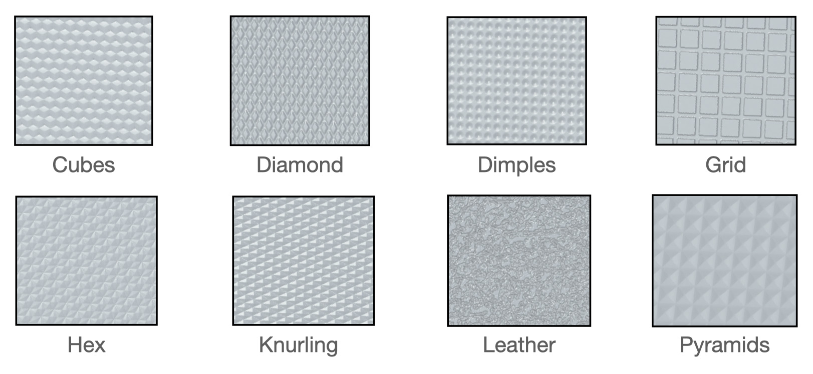
Displacement maps take texture mapping a step further by applying a grayscale image to a texture map and displacing the positions of points on a surface using the grayscale values, creating intricate surface details, and adding depth to the geometry. By manipulating the geometry based on the displacement map, artists and designers can generate complex surface effects such as bumps, wrinkles, tiles, and dents, resulting in more functional and visually compelling designs as shown in Figure 2.
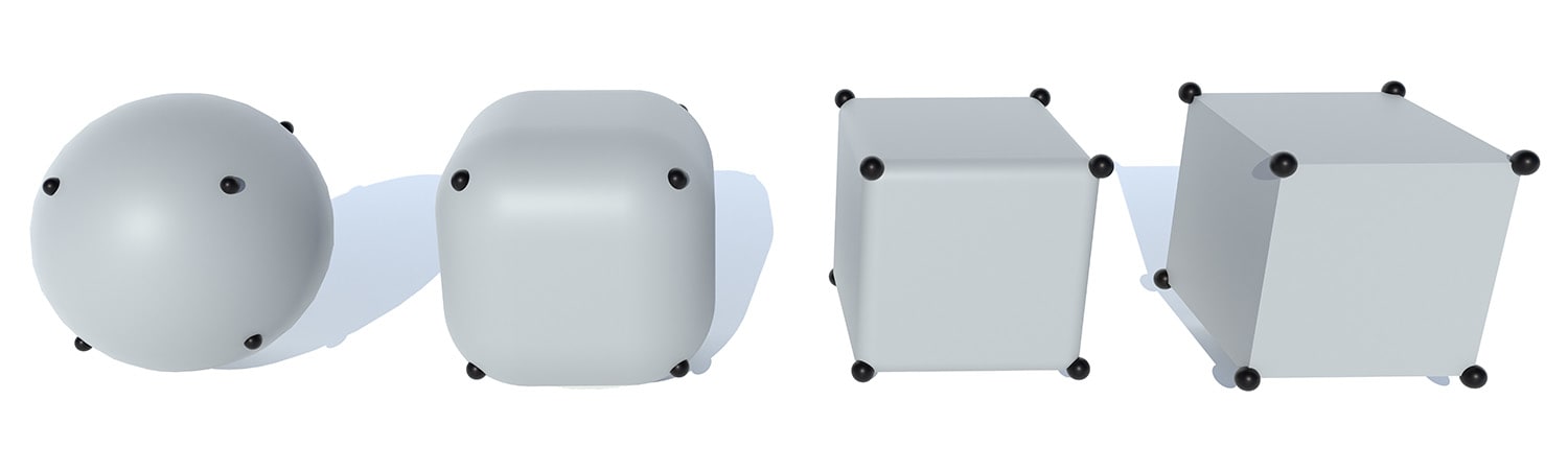
2.1. Discrete conformal equivalence
Mapping three-dimensional shapes onto a two-dimensional plane poses varying levels of difficulty depending on the inherent characteristics of the shape. Take, for example, a sphere and a cube. The process of preserving the shape and area of a sphere when mapping it to a plane can be quite challenging [2]. On the other hand, a cube can be easily cut along its edges and flattened onto the plane. The mathematical intuition behind the vastness in difficulty of these tasks is due to the difference in the distribution of curvature around the two surfaces. On the cube, every point is intrinsically flat (zero curvature) except for the eight “corners”. The sphere however has a uniform distribution of curvature at each vertex. To map a surface to the plane, it must have zero curvature at all internal vertices, and must be a topological disk (Euler characteristic equal to 1 [3]). Thus, a cube can be cut to a disk using a simple graph search algorithm [4] and then laid out in the plane by laying out faces incrementally. We could cut the sphere to a disk as well, but vertices not on the boundary of the cut sphere would have non-zero curvature.
We recognize this simple property in the first step of our algorithm, which is to compute a discrete homeomorphism of our input surface, concentrating curvature to a few special vertices, which we call “cones”. A homeomorphism is a continuous, bijective, invertible function that provides a structure preserving map between shapes. A discrete homeomorphism is applied via per-vertex affine transformations; in the context of texture mapping, we are interested in scaling. Given an edge of a triangle that connects vertices i and j and has length  , we apply per-vertex scale factors
  and
and  to scale the edge length to
  via the formula
 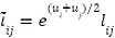 . This formula is derived from the notion of discrete conformal equivalence [5]. In the smooth setting, conformal maps preserve angles, but unfortunately, this definition is far too strict for triangle meshes, since only rigid motion can be applied to triangles if one must preserve all angles. We can however take advantage of the positive metric scaling definition of conformal equivalence, which states that two Riemannian metrics
  and
and  are conformally equivalent if they are related by a positive scaling
  for per vertex scale factors u, which is captured by
  [6]. Unfortunately, discrete homeomorphisms are difficult to implement without creating invalid geometry (as shown in Figure 3). This is because some scale factors will break the triangle inequality (
 ) and thus will invalidate the homeomorphism.

Invalid geometry made it impossible to demonstrate a discrete analog to the Uniformization Theorem, which guarantees that any smooth surface can be conformally mapped to one of constant curvature [7]. It wasn’t until recently that Boris Springborn showed a discrete analog for triangle meshes, which says that any vertex curvatures  can be realized by some vertex scaling u, as long as the triangle mesh data structure is able to represent an equivalence class of shapes, which can be embedded into various geometric spaces [8]. Two years later, a robust data structure called the intrinsic triangle mesh was used to realize Springborn’s discrete analog to the Uniformization theorem [1]. We use this intuition as the basis for our robust texture mapping algorithm.
2.2. Intrinsic Delaunay triangle meshes
Intrinsic triangle meshes serve as the ideal framework for computing discrete homeomorphisms due to their inherent ability to capture surface properties independent of the embedding space. By capturing geometric properties solely with edge lengths, these meshes abstract away the extraneous details of the embedding, allowing for a more robust and accurate analysis of the surface’s intrinsic characteristics. An intrinsic triangle mesh consists of two triangulations, one static, whose connectivity is fixed, and one dynamic, whose connectivity is allowed to change. The static triangulation can be thought of as a standard triangle mesh. Each vertex has coordinates in Euclidean space, and a half-edge data structure describes the connectivity of the vertices. Unlike the static triangulation, we don’t actually care how the dynamic triangulation sits in space. We use the same half-edge data structure to describe connectivity, but we encapsulate geometry solely by storing edge lengths for each half-edge.
Connectivity can be changed by the intrinsic edge-flip [9]. Given an edge that connects two intrinsic triangles, simply break the edge and connect the two vertices on the triangle pair that were not part of the original edge. Oftentimes, we determine if an edge should be “flipped” by determining if it is Delaunay. An edge is intrinsically Delaunay if the sum of its opposing angles is less than 𝜋 radians. If this condition is satisfied globally, we are left with an intrinsic Delaunay triangulation[9]. These meshes exhibit a wide range of good-behavior for numerically sensitive algorithms, like parameterization [10]. To track how the static and dynamic triangulations interact with each other, we leverage the integer connectivity scheme [11] which utilizes normal coordinates [12] from algebraic topology to implicitly capture crossings of static and dynamic edges, the latter of which are thought of as geodesic curves.

2.3. The hyperbolic picture
As mentioned in Section 2.1, the triangle inequality can break for certain scale factors, which invalidates the Euclidean metric and creates invalid geometry. However, we can apply arbitrary vertex scaling in the hyperbolic setting by realizing our surface as an ideal hyperbolic polyhedron [13]. To execute this realization, we assign Penner coordinates  for each edge, where
  . Recall the conformal Riemannian metric described by . By substituting the formula for in terms of Penner coordinates and simplifying, we get an equivalent definition of the conformal Riemannian metric in terms of Penner coordinates
  . An equivalent definition of the triangle inequality is then
  . This inequality is always valid, regardless of the scale factors , . Thus, by utilizing our flexible equivalence class data structure (the intrinsic triangle mesh), we can apply arbitrary vertex scalings, and yield valid hyperbolic geometry, even in cases where the Euclidean metric becomes invalid. One can always convert a Euclidean edge length to a Penner coordinate, and then apply arbitrary vertex scale factors to yield valid hyperbolic geometry. We could apply the formula
  to yield Euclidean edge lengths, but this may yield invalid geometry. One can rectify this issue by applying a greedy edge-flipping algorithm (using the Ptolemy relation [13]) for each edge that does not satisfy the local ideal Delaunay condition [1]. Remarkably, if this condition is satisfied globally, the edge lengths l describe an intrinsic Delaunay triangulation in the hyperbolic and Euclidean case [8]. The intrinsic Delaunay condition is also always recoverable [9] which means that we can embed our surface into hyperbolic space, apply any vertex scaling, apply a greedy edge flipping algorithm using Ptolemy flips, and yield a valid Euclidean metric.
2.4. Minimizing conformal energy
With intrinsic triangulations and Ptolemy flips, we can use any convex minimizer to yield the scale factors  , which induce an intrinsically flat surface M̃. At each iteration, the curvature of the surfaces incrementally concentrates around cones (see Section 2.5), which serve as constraints during optimization.
2.5. Full parameterization pipeline
After calculating M̃, we cut it to a topological disk using a simple graph search algorithm [4]. To assign UV coordinates to every vertex of the cut mesh, we use the robust “layout in the light cone” method of [14]. This yields two vertex coordinates  and
and  for the original and UV projected mesh, respectively. We use the projective interpolation method [1] which is achieved by performing linear interpolation on homogeneous coordinates
  and
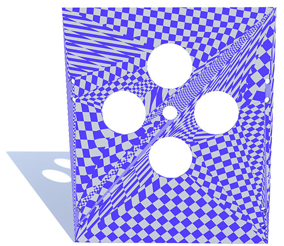
and  for a vertex scale factor . This interpolation scheme can be visualized by tiling a checkerboard texture over the original surface (as shown in Figure 6).

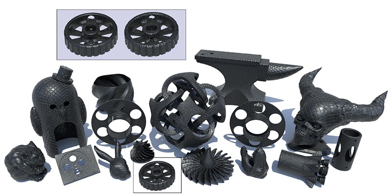
Sample points on the surface and perturbing them according to some tileable texture function allows the user to generate textured meshes, which can immediately be sent to the printer for manufacturing. Textured versions of computationally challenging models from the Thingi10k dataset are shown in Figure 7.
3. Intrinsic mesh algorithms can handle poor triangulations
As mentioned earlier, texture mapping is the critical mathematical problem that must be addressed to enable the utilization of displacement maps. Unfortunately, the performance of most texture mapping algorithms is inherently linked to the quality of the input triangulation. In the context of the Carbon ecosystem, where triangle meshes are frequently derived from CAD systems, most models are poorly triangulated (high aspect ratio, skinny triangles) as shown in Figure 8.

These triangulations can pose difficulties for texturing algorithms (Figure 9 shows a highly distorted texture map using Boundary First Flattening [15]), potentially resulting in distortions and inaccuracies in the mapping. Therefore, addressing triangulation quality becomes a crucial consideration to ensure optimal texture mapping and subsequently enable the successful implementation of displacement maps.
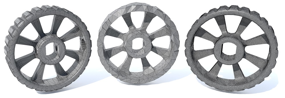
The standard approach to rectify poor triangulations is to extrinsically remesh the surface. Extrinsic remeshing involves generating a new mesh with improved triangle quality by redistributing vertices and creating new triangles. Unfortunately, remeshing introduces a fundamental tradeoff between mesh size (number of faces) and geometric accuracy. As the remeshing process strives to bring the new mesh closer to the original surface geometrically, the number of triangles significantly increases (as shown in Figure 10). This increase in mesh size can pose challenges for downstream algorithms, making them more computationally intensive and harder to solve. Therefore, there is a delicate balance between achieving a geometrically accurate representation of the surface and maintaining a manageable mesh size for efficient processing and algorithmic feasibility.
Optimal triangle meshes for geometric computation are often difficult to realize, since they inherently try to have two properties: encode the shape of the original surface (geometric accuracy), and serve as a useful domain for computation (isotropic, low aspect-ratio triangles). This paradigm is broken by the intrinsic triangle mesh. The static triangulation encodes the shape exactly, while the dynamic triangulation encodes the domain for computation. With intrinsic edge flips, we can vastly improve computational results without changing algorithms. We simply run a computational geometry algorithm on the dynamic triangulation of the intrinsic triangle mesh, then transfer the results to the original triangulation, enabling out-of-the-box robustness improvements on a wide variety of geometry processing algorithms.
References
- ^ Mark Gillespie, Boris Springborn, and Keenan Crane. “Discrete Conformal Equivalence of Polyhedral Surfaces”. ACM Transactions on Graphics. 40.4 (July 2021). ISSN: 0730-0301. DOI: 10.1145/3450626.3459763. https://doi.org/10.1145/3450626.3459763
- ^ John Parr Snyder. Flattening the earth two thousand years of map projections. The University of Chicago Press, 2002.
- ^Xianfeng David Gu and Shing-Tung Yau. Computational conformal geometry. International Press, 2008.
- ^Jeff Erickson and Kim Whittlesey. “Greedy Optimal Homotopy and Homology Generators”. Proceedings of the Sixteenth Annual ACM-SIAM Symposium on Discrete Algorithms. SODA ’05. Vancouver, British Columbia: Society for Industrial and Applied Mathematics, 2005, pp. 1038–1046. ISBN: 0898715857.
- ^M. Rocek and R. M. Williams. “The Quantization of Regge Calculus”.Z. Phys. C 21 (1984), p. 371. DOI: 10.1007/BF01581603.
- ^Feng Luo. Combinatorial Yamabe Flow on Surfaces.2003. arXiv: math/0306167 [math.GT]
- ^William Abikoff. “The Uniformization Theorem”. The American Mathematical Monthly 88.8 (1981), pp. 574–592. DOI: 10.1080/00029890.1981.11995320.eprint: https://doi.org/10.1080/00029890.1981.11995320
- ^Boris Springborn. “Ideal Hyperbolic Polyhedra and Discrete Uniformization”. Discrete & Computational Geometry 64 (2020), pp. 63–108.
- ^Nicholas Sharp, Yousuf Soliman, and Keenan Crane. “Navigating Intrinsic Triangulations”. ACM Trans. Graph. 38.4 (July 2019). ISSN: 0730-0301. DOI:
10.1145/3306346.3322979. https://doi.org/10.1145/3306346.3322979 - ^Alexander I. Bobenko and Boris A. Springborn. “A Discrete Laplace—Beltrami Operator
for Simplicial Surfaces”. Discrete Comput. Geom. 38.4 (Dec. 2007), pp. 740–756. ISSN: 0179-5376. - ^Mark Gillespie, Nicholas Sharp, and Keenan Crane. Integer Coordinates for Intrinsic Geometry Processing. 2021. arXiv: 2106.00220 [cs.GR].
- ^Jeff Erickson and Amir Nayyeri. “Tracing Compressed Curves in Triangulated Surfaces”. In: Proceedings of the Twenty-Eighth Annual Symposium on Computational Geometry. SoCG ’12. Chapel Hill, North Carolina, USA: Association for Computing Machinery, 2012, pp. 131–140. ISBN: 9781450312998. DOI: 10.1145/2261250.2261270. https://doi.org/10.1145/2261250.2261270
- ^Robert C. Penner. Decorated teichmüller theory. European Mathematical Society, 2012.
- ^Patrick Mullen et al. “Spectral Conformal Parameterization”. Proceedings of the Symposium on Geometry Processing. SGP ’08. Copenhagen, Denmark: Eurographics Association, 2008, pp. 1487–1494.
- ^Rohan Sawhney and Keenan Crane. “Boundary First Flattening”. ACM Trans. Graph.
37.1 (Dec. 2017). ISSN: 0730-0301. DOI: 10.1145/3132705. https://doi.org/10.1145/3132705
3D as It’s Meant to Be
Interested in utilizing Carbon to accelerate product development? Reach out to us at sales@carbon3d.com to learn more!