
Carbon DLS Accuracy for Engineering Materials
The Carbon DLS™ process has accuracy and repeatability capabilities that depend on resin and part geometry. General Accuracy is described as a constant offset plus a ratio, for example, ±70 μm +1 μm per mm dimension size. General Accuracy is what you could expect when first printing any given geometry. After a part has been optimized for production, some of the sources of variation are removed. The remaining variation is cited as Production Repeatability.
Previously, we gave very conservative high-level guidance around our tolerances. We now offer more granular guidance based on several years’ worth of CT scans and field data on both general first-print accuracy and production accuracy following process optimization. The following figures are a summary of the updated guidelines, followed by a deeper dive into the data itself.
| Metric Units | ±65 μm + 1 μm per mm dimension size |
| Imperial Units | Up to ±0.003 in + 0.001 in per in dimension size |
| Metric Units | Up to ±35 μm |
| Imperial Units | Up to ±0.002 in |
Accuracy Definitions
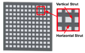
Two numbers describe the general accuracy capabilities of the Carbon DLS process: 1) the constant offset and 2) the dimensionally-dependent μm per mm. The constant offset is determined by the stack-up of variation sources that affect what we call “local offset accuracy.” This is measured with a test part that has both horizontal and vertical struts (below). Excess curing of the vertical and horizontal struts is called “overcure” and “cure-thru,” respectively.
The second number that describes accuracy is a factor that is multiplied by the length of the dimensional span. In this way, larger spans are expected to have larger deviations from nominal dimensions compared to smaller spans. These values are meant to include inaccuracies due to uniform part shrinkage and warpage (i.e., non-uniform shrinkage). The values are determined from a series of stair-step test parts with different wall thicknesses. The percentage we report is determined by subtracting the shrinkage of the 3-mm wall thickness part from that of the 1-mm part.
Sources of Variation That Affect Local Offset Accuracy
- Lot-to-lot variation in resin characteristics
- Printer-to-printer light engine peak wavelength
- Build area variation across the printer
- Temperature variation during printing
- Print speed variation
- Resin pot life age
- Variation in lab environment
Accuracy Data
| General Accuracy | Production Repeatability (95% of points) |
|||
|---|---|---|---|---|
| Resin | M1, M2, L1 | M3, M3 Max | M1, M2, L1 | M3, M3 Max |
| MPU 100 | ±85 μm + 2 μm/mm | ±70 μm + 2 μm/mm | ±60 μm + 1 μm/mm | ±50 μm + 1 μm/mm |
| UMA 90 | ±80 μm + 2 μm/mm | ±60 μm + 2 μm/mm | ±50 μm + 1 μm/mm | ±40 μm + 1 μm/mm |
| RPU 70 | ±85 μm + 12 μm/mm | ±65 μm + 12 μm/mm | ±55 μm + 1 μm/mm | ±40 μm + 1 μm/mm |
| RPU 130 | ±80 μm + 19 μm/mm | ±60 μm + 19 μm/mm | ±55 μm + 1 μm/mm | ±35 μm + 1 μm/mm |
| FPU 50 | ±85 μm + 12 μm/mm | ±65 μm + 12 μm/mm | ±55 μm + 1 μm/mm | ±40 μm + 1 μm/mm |
| EPX 82 | ±75 μm + 14 μm/mm | ±55 μm + 14 μm/mm | ±40 μm + 1 μm/mm | ±40 μm + 1 μm/mm |
| EPX 86FR | ±80 um + 7 μm/mm | ±60 μm + 7 μm/mm | ±50 μm + 1 μm/mm | ±40 μm + 1 μm/mm |
| EPX 150 | ±75 μm + 10 μm/mm | ±50 μm + 10 μm/mm | ±35 μm + 1 μm/mm | ±35 μm + 1 μm/mm |
| EPU 40 | ±80 μm + 11 μm/mm | ±65 μm + 11 μm/mm | ±55 μm + 1 μm/mm | ±35 μm + 1 μm/mm |
| EPU 41 | ±65 μm + 11 μm/mm | ±50 μm + 11 μm/mm | ±40 μm + 1 μm/mm | ±35 μm + 1 μm/mm |
| EPU 43 | ±75 μm + 5 μm/mm | ±60μm + 5 μm/mm | ±50 μm + 1 μm/mm | ±35 μm + 1 μm/mm |
| EPU 45 | ±75 μm + 14 μm/mm | ±60 μm + 14 μm/mm | ±55 μm + 1 μm/mm | ±35 μm + 1 μm/mm |
| EPU 46 Regular | ±110 μm + 10 μm/mm | ±100 μm + 10 μm/mm | ±55 μm + 1 μm/mm | ±35 μm + 1 μm/mm |
| EPU 46 Soft | ±110 μm + 10 μm/mm | ±100 μm + 10 μm/mm | ±55 μm + 1 μm/mm | ±35 μm + 1 μm/mm |
| EPU 46 Extra Soft | ±110 μm + 10 μm/mm | ±100 μm + 10 μm/mm | ±55 μm + 1 μm/mm | ±35 μm + 1 μm/mm |
| SIL 30 | ±135 μm + 19 μm/mm | ±130 μm + 19 μm/mm | ±80 μm + 1 μm/mm | ±80 μm + 1 μm/mm |
| Loctite 147 | ±85 μm + 2 μm/mm (estimate) | ±75 μm + 2 μm/mm (estimate) | ±50 μm + 1 μm/mm (estimate) | ±50 μm + 1 μm/mm (estimate) |
| Loctite 3843 | ±85 μm + 2 μm/mm (estimate) | ±75 μm + 2 μm/mm (estimate) | ±50 μm + 1 μm/mm (estimate) | ±50 μm + 1 μm/mm (estimate) |
| Henkel IND 405 Clear | ±120 μm + 5 μm/mm (estimate) | ±115 μm + 5 μm/mm (estimate) | ±75 μm + 1 μm/mm (estimate) | ±60 μm + 1 μm/mm (estimate) |
| General Accuracy | Production Repeatability (95% of points) |
|||
|---|---|---|---|---|
| Resin | M1, M2, L1 | M3, M3 Max | M1, M2, L1 | M3, M3 Max |
| MPU 100 | ±0.0034 in + 0.002 in/in | ±0.0028 in + 0.002 in/in | ±0.0024 in + 0.001 in/in | ±0.002 in + 0.001 in/in |
| UMA 90 | ±0.0032 in + 0.002 in/in | ±0.0024 in + 0.002 in/in | ±0.002 in + 0.001 in/in | ±0.0016 in + 0.001 in/in |
| RPU 70 | ±0.0034 in + 0.012 in/in | ±0.0026 in + 0.012 in/in | ±0.0022 in + 0.001 in/in | ±0.0016 in + 0.001 in/in |
| RPU 130 | ±0.0032 in + 0.019 in/in | ±0.0024 in + 0.019 in/in | ±0.0022 in + 0.001 in/in | ±0.0014 in + 0.001 in/in |
| FPU 50 | ±0.0034 in + 0.012 in/in | ±0.0026 in + 0.012 in/in | ±0.0022 in + 0.001 in/in | ±0.0016 in + 0.001 in/in |
| EPX 82 | ±0.003 in + 0.014 in/in | ±0.0022 in + 0.014 in/in | ±0.0016 in + 0.001 in/in | ±0.0016 in + 0.001 in/in |
| EPX 86FR | ±0.0032 in + 0.007 in/in | ±0.0024 in + 0.007 in/in | ±0.002 in + 0.001 in/in | ±0.0016 in + 0.001 in/in |
| EPX 150 | ±0.003 in + 0.01 in/in | ±0.002 in + 0.01 in/in | ±0.0014 in + 0.001 in/in | ±0.0014 in + 0.001 in/in |
| EPU 40 | ±0.0032 in + 0.011 in/in | ±0.0026in + 0.011 in/in | ±0.0022 in + 0.001 in/in | ±0.0014 in + 0.001 in/in |
| EPU 41 | ±0.0026 in + 0.011 in/in | ±0.002 in + 0.011 in/in | ±0.0016 in + 0.001 in/in | ±0.0014 in + 0.001 in/in |
| EPU 43 | ±0.003 in + 0.005 in/in | ±0.0024 in + 0.005 in/in | ±0.002 in + 0.001 in/in | ±0.0014 in + 0.001 in/in |
| EPU 45 | ±0.003 in + 0.014 in/in | ±0.0024 in + 0.014 in/in | ±0.0022 in + 0.001 in/in | ±0.0014 in + 0.001 in/in |
| EPU 46 Regular | ±0.0044 in + 0.01 in/in | ±0.004 in + 0.01 in/in | ±0.0022 in + 0.001 in/in | ±0.0014 in + 0.001 in/in |
| EPU 46 Soft | ±0.0044 in + 0.01 in/in | ±0.004 in + 0.01 in/in | ±0.0022 in + 0.001 in/in | ±0.0014 in + 0.001 in/in |
| EPU 46 Extra Soft | ±0.0044 in + 0.01 in/in | ±0.004 in + 0.01 in/in | ±0.0022 in + 0.001 in/in | ±0.0014 in + 0.001 in/in |
| SIL 30 | ±0.0054 in + 0.019 in/in | ±0.0052 in + 0.019 in/in | ±0.0032 in + 0.001 in/in | ±0.0032 in + 0.001 in/in |
| Loctite 147 | ±0.0034 in + 0.002 in/in (estimate) | ±0.003 in + 0.002 in/in (estimate) | ±0.002 in + 0.001 in/in (estimate) | ±0.002 in + 0.001 in/in (estimate) |
| Loctite 3843 | ±0.0034 in + 0.002 in/in (estimate) | ±0.003 in + 0.002 in/in (estimate) | ±0.002 in + 0.001 in/in (estimate) | ±0.002 in + 0.001 in/in (estimate) |
| Henkel IND 405 Clear | ±0.0048 in + 0.005 in/in (estimate) | ±0.0046 in + 0.005 in/in (estimate) | ±0.003 in + 0.001 in/in (estimate) | ±0.0024 in + 0.001 in/in (estimate) |